Pillow flipping machine
In this article we will go along the process of how we created this node for a pillow technological line.
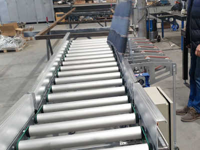
Here is a glimpse of the final product:
First step -> CAD
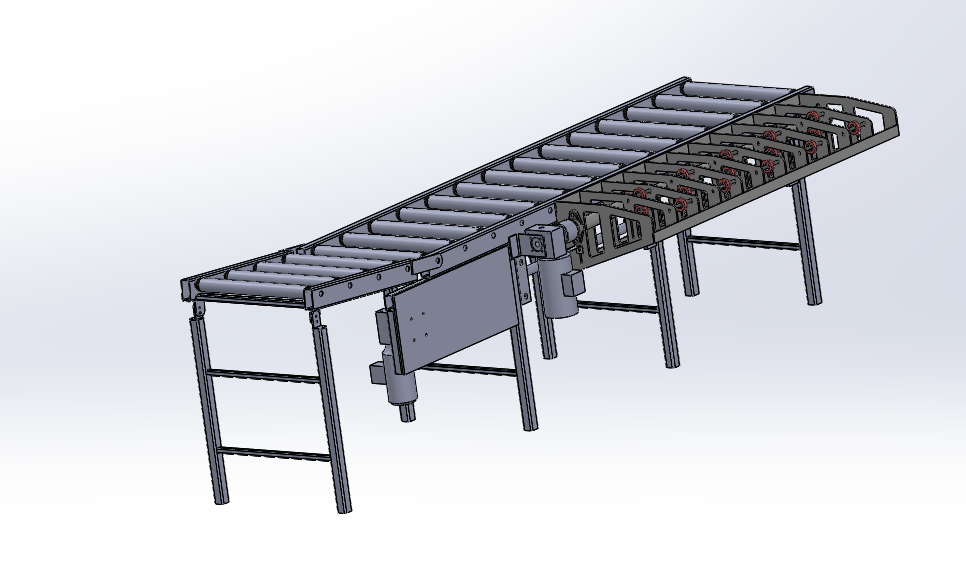
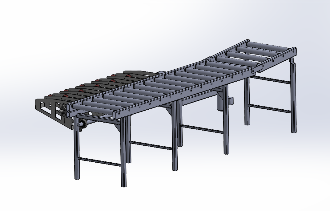
After we get our client requirements the majority of our projects starts with our CAD design where we make sure everything fits and make sense:
Mechanical work
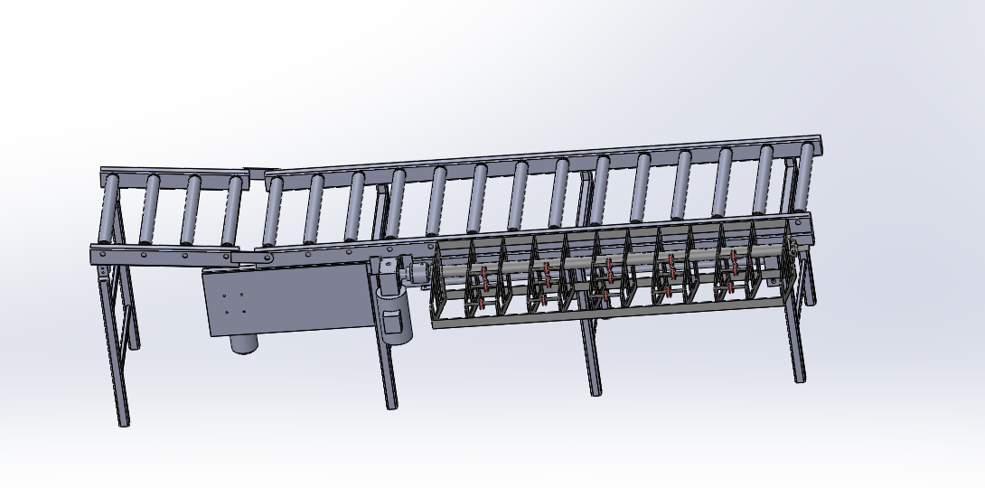
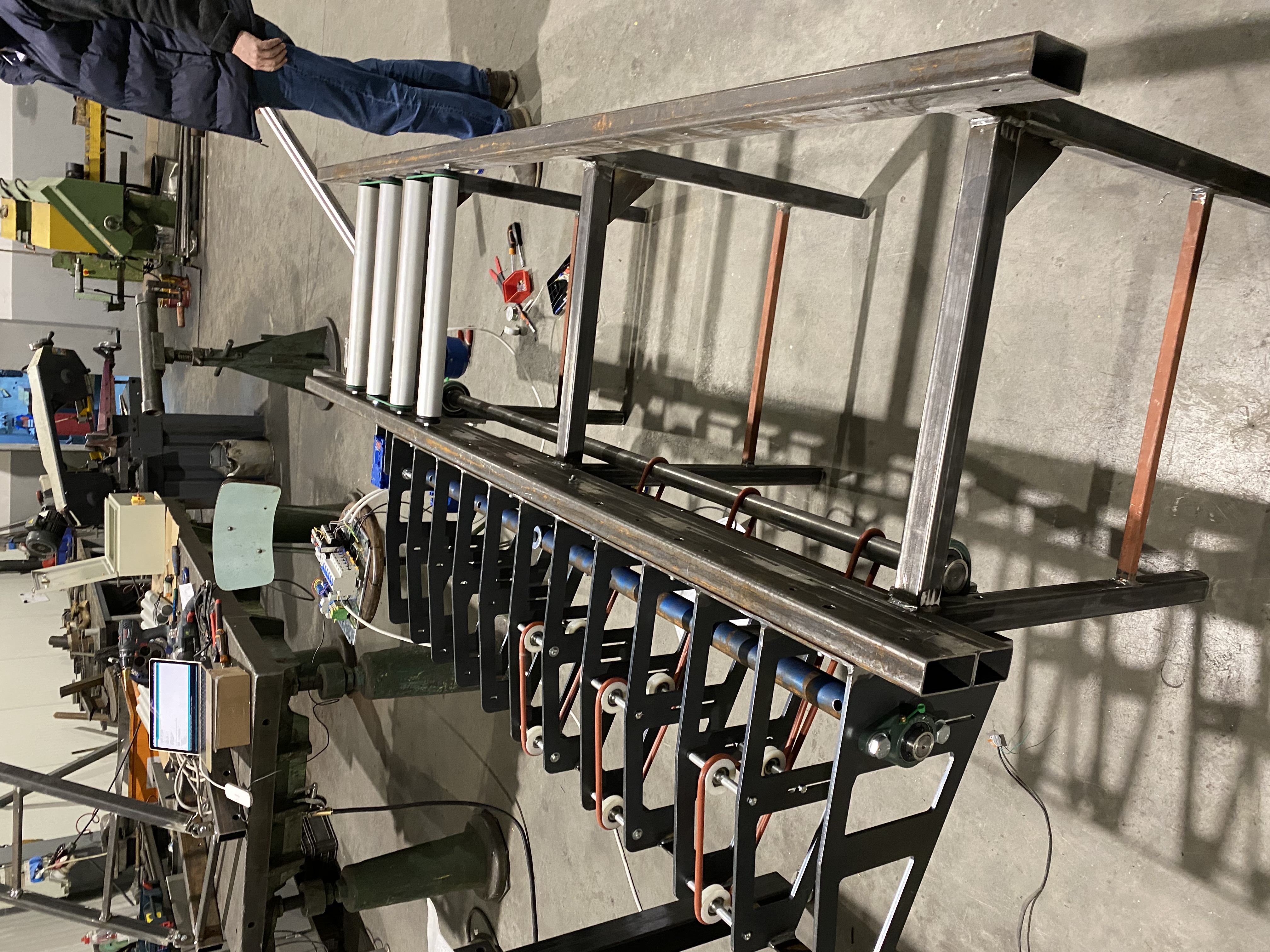
Once the CAD meets our standards we can start working on the mechanical part. You can see an intermediate step here:
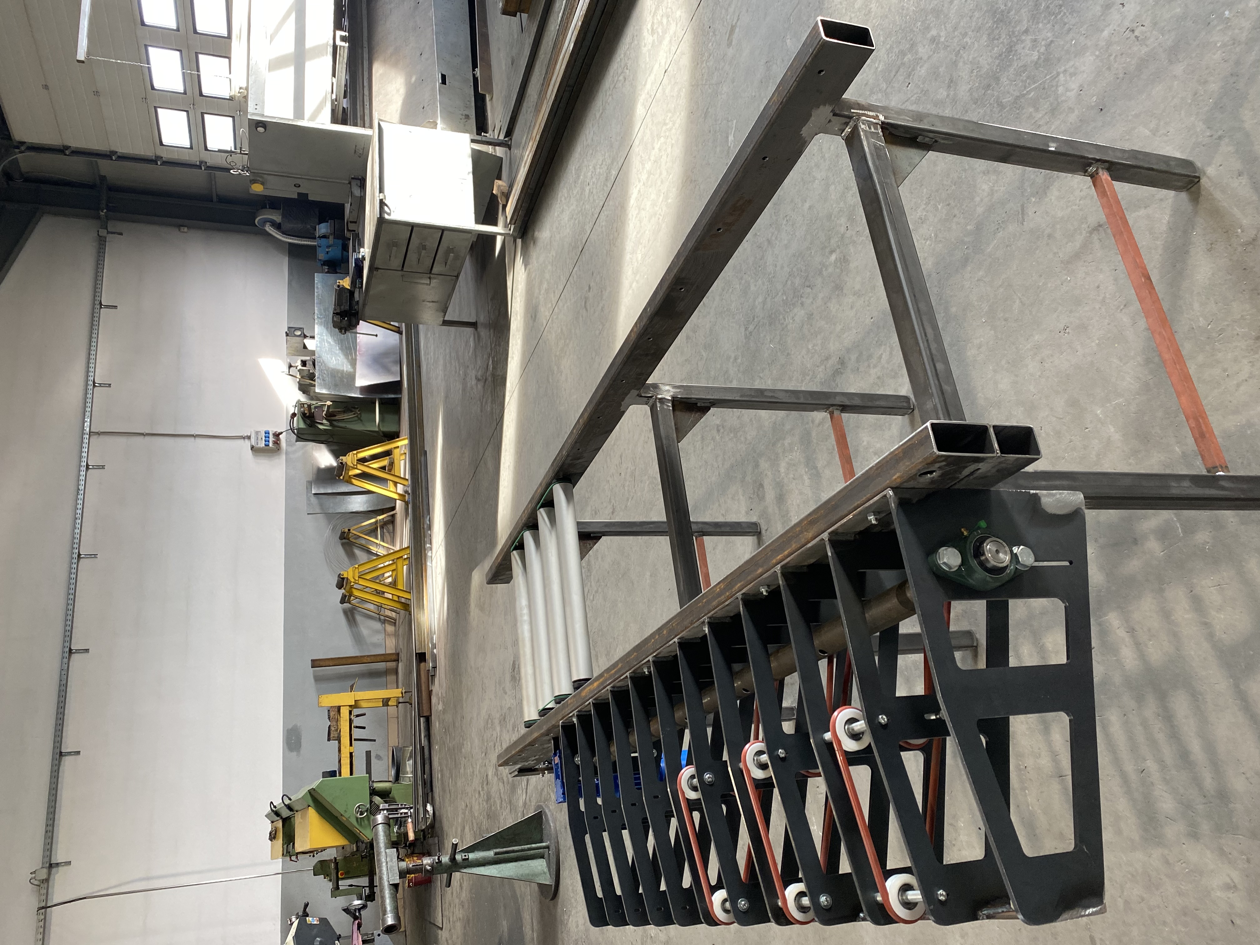
Once we have a functional system that covers most of the mechanical work we can start linking it to the electrical counterpart.
Electrical work
Electrical work always starts with buying all the components and waiting for their arrival...
Here they are:

We can start our actual work now. Our electrical system will be composed of the following:
- Our brain will be an arduino micro
- One optical sensor for reading the pillow position
- One inductive sensor to read motor that flippes the pillow rotation
- One relay to apply the break on the flipping motor
- One potentiometer
- Two 380v motors with demultiplier
- Fuses
- Control light
- 380v commutators
First try
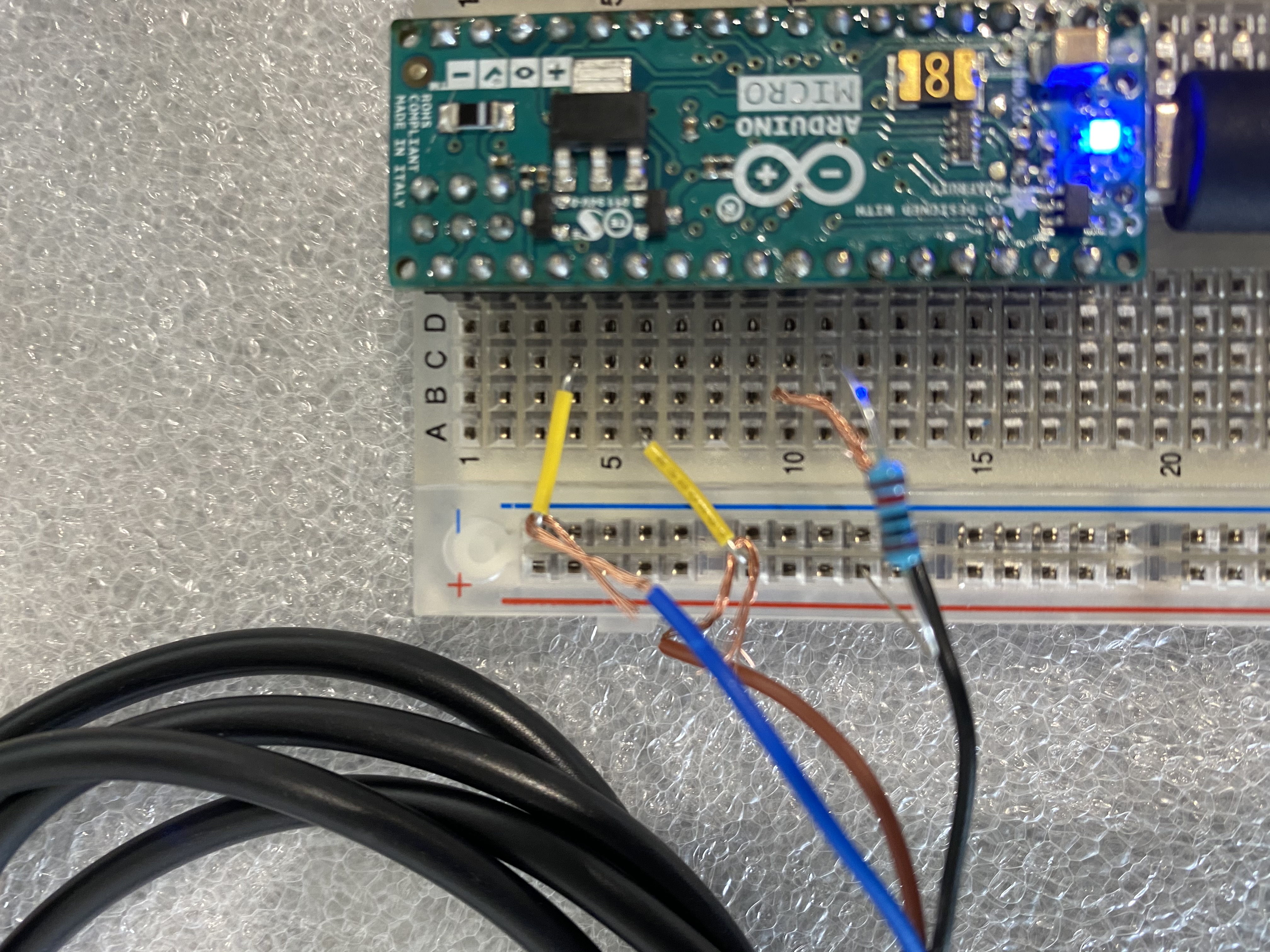
Yeap, we had a first try that ended in ruins ¯_(ツ)_/¯. But this is always a good oportunity to learn more and expand our knowledge/ So to give you more context we wanted to use an induction senzor, an IFM induction sensor to read motor half turns. This senzor has a 5V-24V and is a two wire one. You can see the senzor and the wireing in the following pictures:
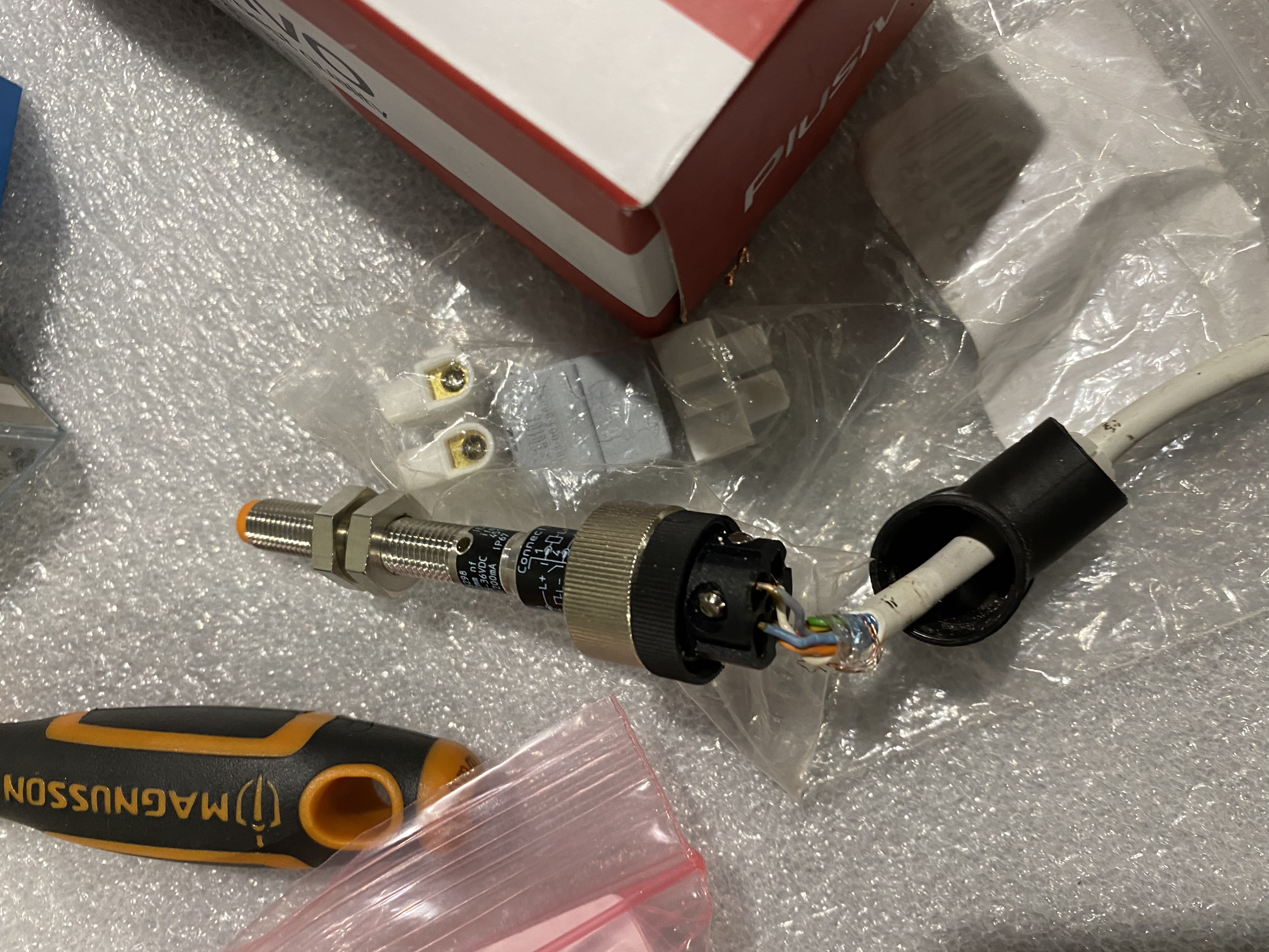

But for the love of god I wasn't able to make it work with my arduino. Tried different approaches but nothing seemed to work.
I figured I need to simplify my testing, remove as many components as possible and put a load on the senzor. So I started by putting 24V (went with the automation standard just to be sure) and GND on the senzor made the control led work accordingly. That was a small victory. But once I put some load on it, a standard relay like this:
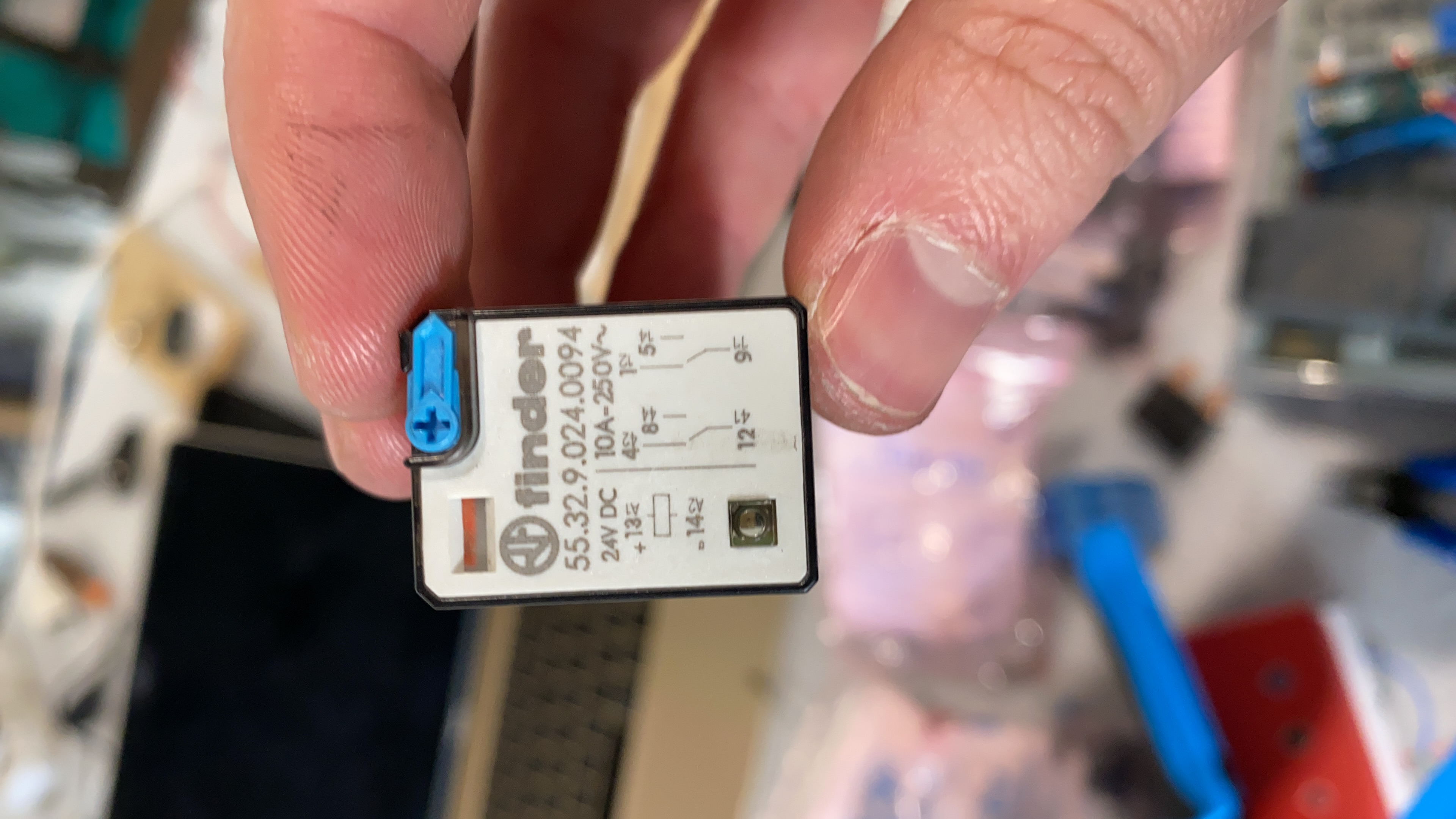

The sensor wasn't able to make the relay work so I think it was busted.
Right way
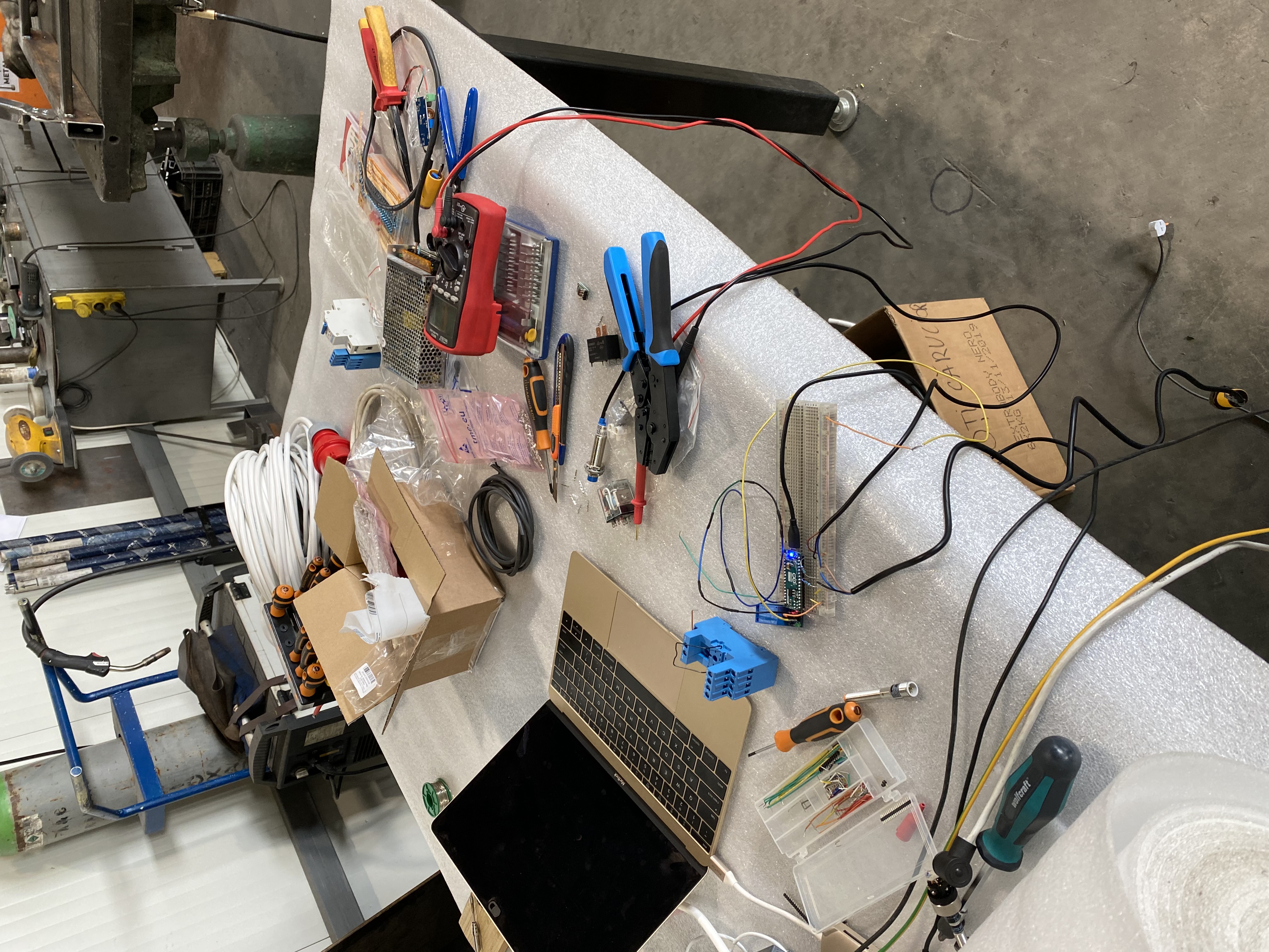
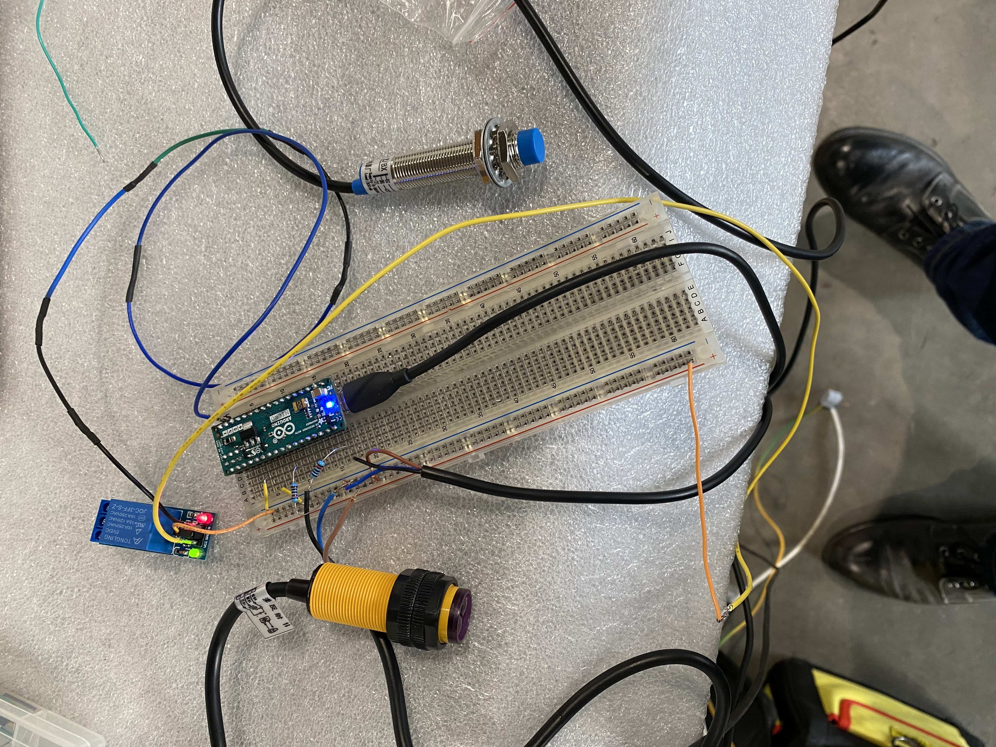
After my first try I pulled all my electronics out on the table to use all my tools in my toolbox to figure out what the problem wa. I was only able to make a mess of our workstation:
For the second approach we want with 3-wire sensors and all worked like a charm. This is the final prototype:
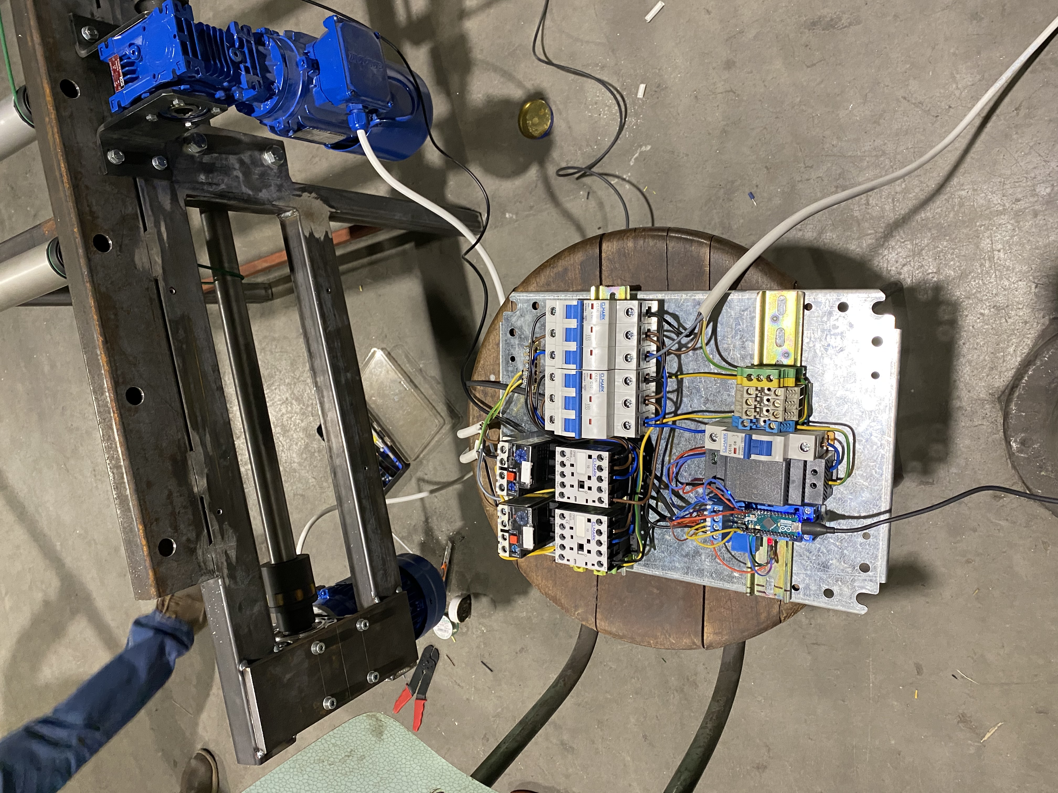
Electric box
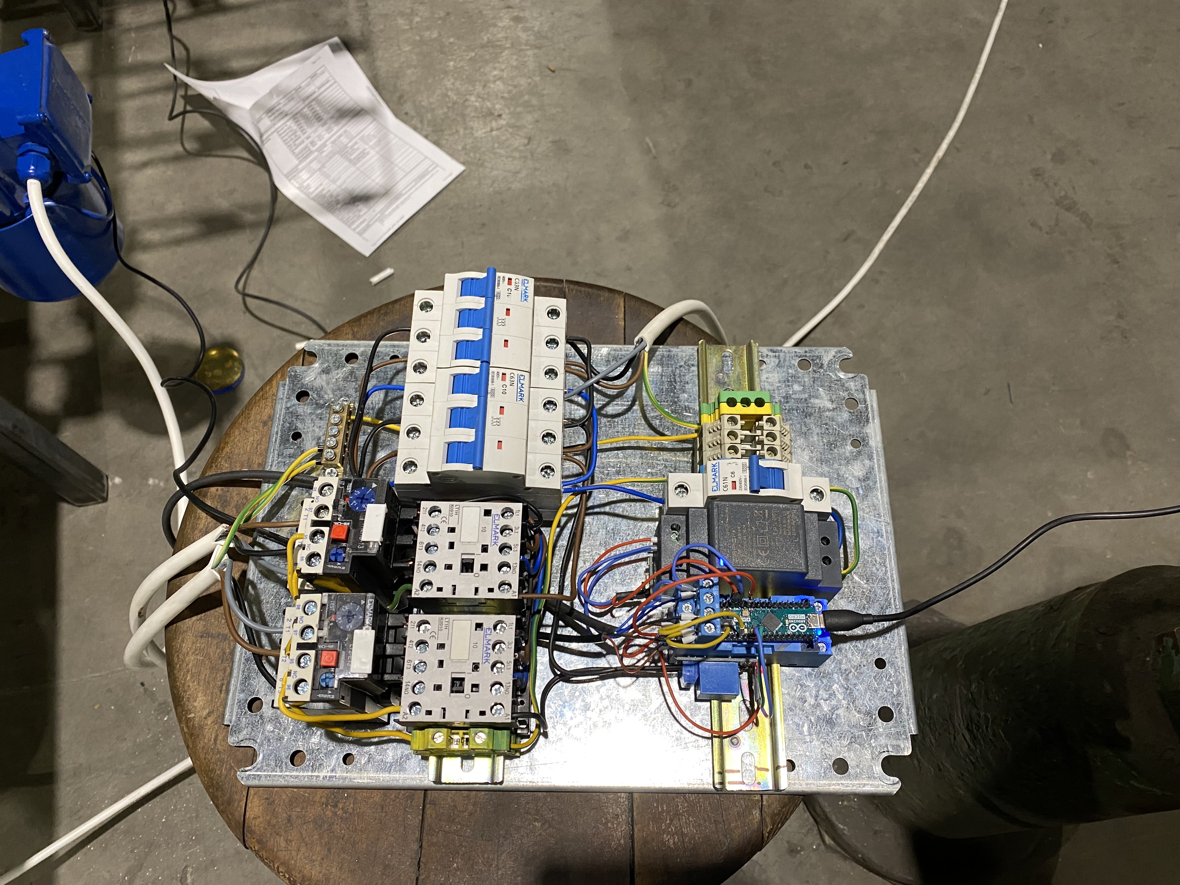
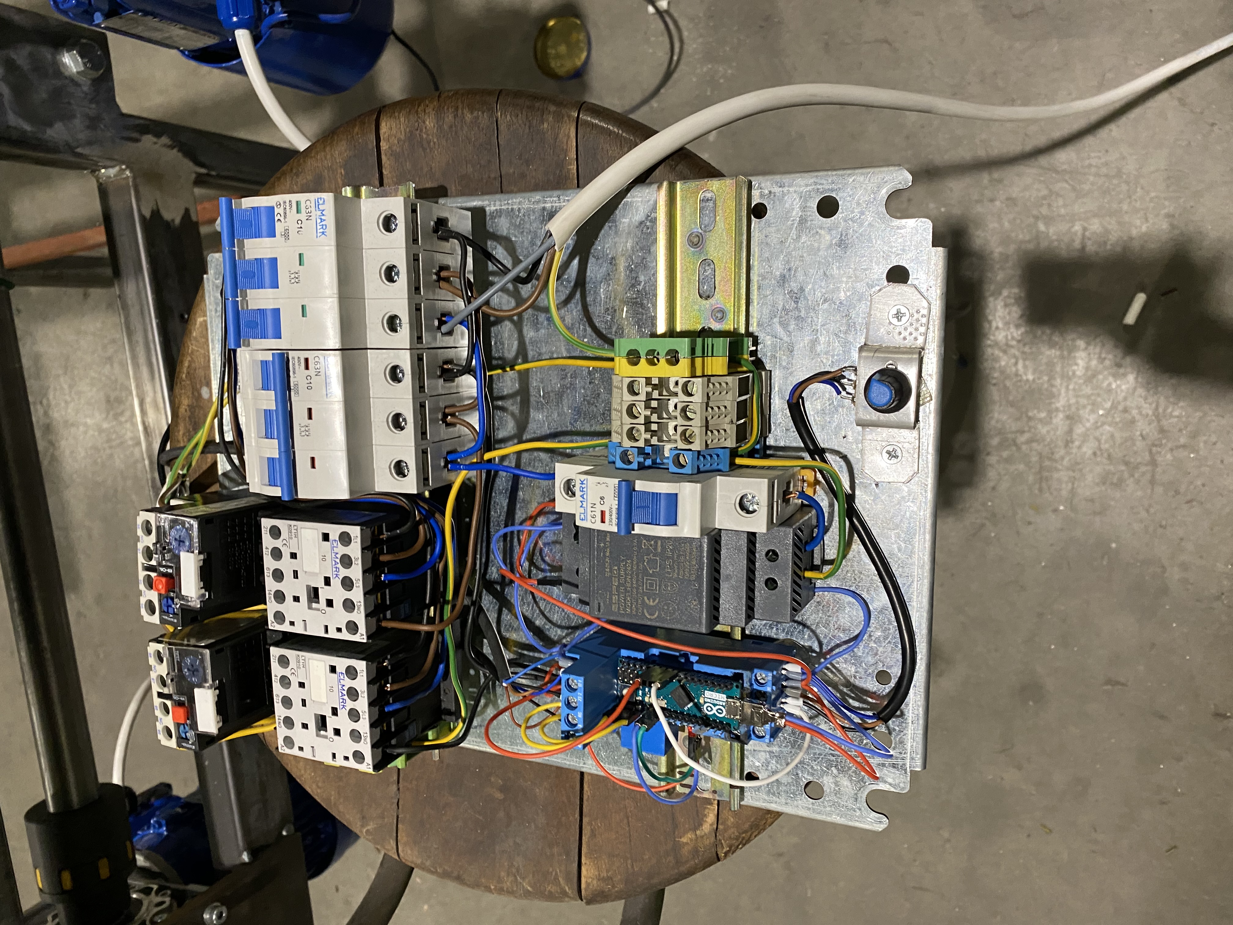
Once the prototype was finished we could work on the electric box. We wanted to put the brain, fuses, commutators and control lamps and all the wiring. This is the final look of the inside of the electric box:
First try
With all the electronics in place, I coupled them to the mechanical counterparts and we gave it a shoot:
With a small exception all went acording to plan. A small hiccup that we fixed relatively easy was that the spinning motor was over-spinning. The problem was that I had my arduino work on a slow pace when I did my prototyping. It was as easy as changeing a line and we were back in business.
Once everything was working we had to unscrew everything so that we can paint all the components.